Sign up for our newsletter!
Your data will be handled in compliance with our privacy policy.
Your data will be handled in compliance with our privacy policy.

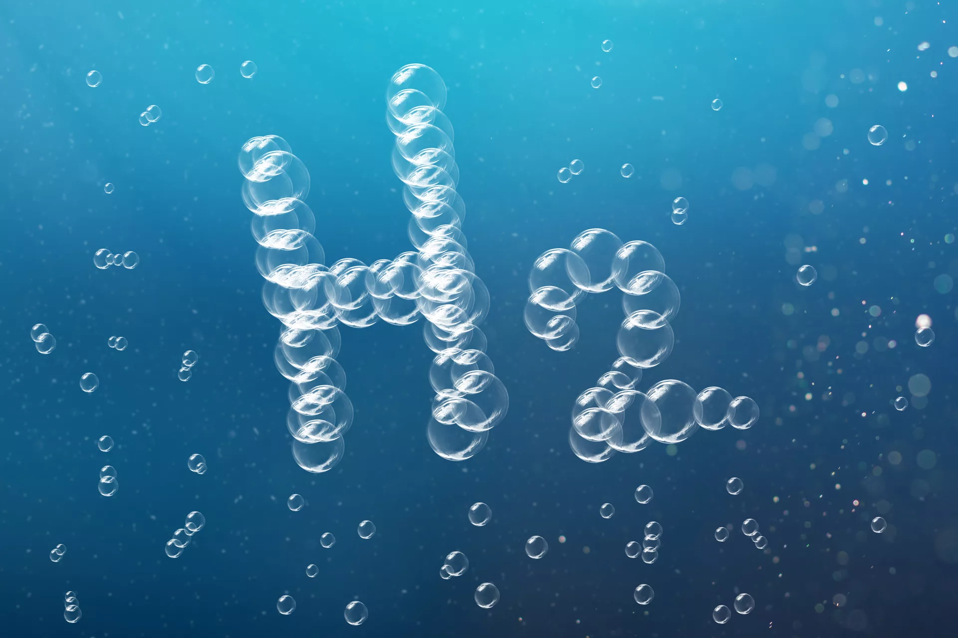
Carbon nanofibers in hydrogen electrolysis & fuel cells Hydrogen has emerged as a key to store renewable energy and making heavy industry carbon-free. Two application areas of immediate vital importance. The core technologies that make this possible are hydrogen electrolysis and fuel cells. Electrolysis converts electricity into hydrogen, while fuel cells convert the hydrogen back to electricity.
Thomas Barregren • November 6, 2021
Hydrogen has emerged as a key to store renewable energy and making heavy industry carbon-free. Two application areas of immediate vital importance. The core technologies that make this possible are hydrogen electrolysis and fuel cells. Electrolysis converts electricity into hydrogen, while fuel cells convert the hydrogen back to electricity. Naturally, these conversions are subject to energy losses. Unfortunately, these losses can be pretty significant—up to eighty percent. However, there are solutions, and carbon nanofiber (CNF) is part of them.
The intermittent nature of renewable energy sources such as solar and wind power creates a demand for solutions to store surplus electricity produced on sunny or windy days for later use. One method of storing surplus electricity is to convert it into hydrogen by electrolysis of water. Fuel cells can then convert the hydrogen back into electricity.
Hydrogen is expected to become increasingly important as a fuel. Hydrogen-powered vehicles are already on the road today. There are even hydrogen-powered passenger cars available for anyone to buy.
Not least, hydrogen is an increasingly essential raw material in heavy industry. For example, hydrogen is replacing coal and coke in the production of steel, enabling fossil-free steel production.
Hydrogen is produced industrially in electrolyzers. Basically, an electrolyzer can be described as a tank of water in which two electrodes are immersed. When an electric voltage is applied across the electrodes, a current flows through the water. The current breaks down the water into its constituent parts: hydrogen and oxygen. Hydrogen bubbles up at one of the electrodes. Oxygen at the other.
The oldest and most conventional way of producing hydrogen is alkaline electrolysis.
In this process, lye (potassium hydroxide or sodium hydroxide) is added to the water, making it highly corrosive. The electrodes, made of nickel alloy, are separated by a membrane which allows hydroxide ions (OH-) to flow through, on their way from the cathode to the anode, while separating the hydrogen gas produced at one electrode from the oxygen gas produced at the other.
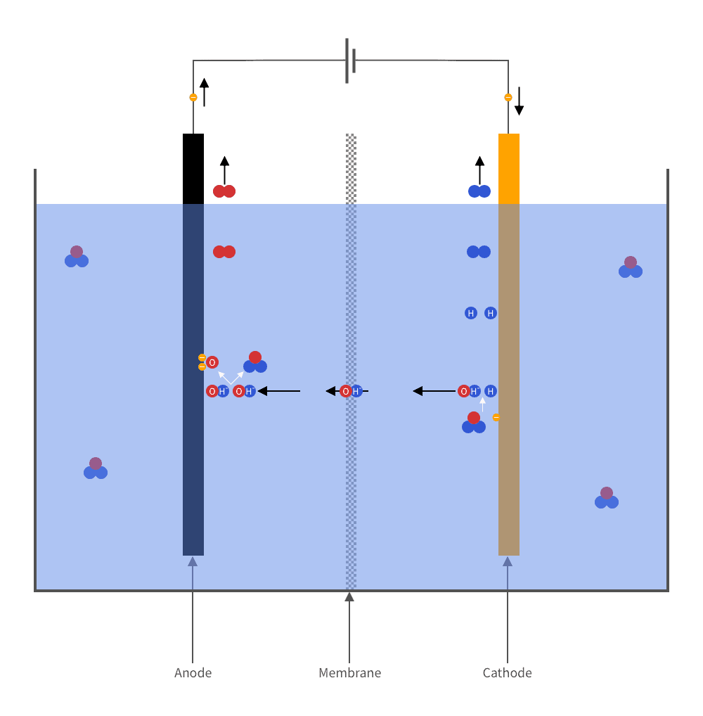
This technique has several disadvantages. Mainly is the low efficiency. The energy value of the hydrogen generated is only 45–65% of the energy supplied. In addition, the method works poorly for renewable electricity because of its intermittent nature.
There are alternatives to conventional alkaline electrolysis. The table below summarizes the most common solutions.
| Type | Membrane | Electrolyte | Catalyst | Current density [A/cm2] | Operational temperature [°C] |
|---|---|---|---|---|---|
| Alkaline electrolyzer | Diaphragm | KOH dissolved in water | Non-noble metal alloys | 0.2–0.7 | 60–80 |
| High-temperature electrolyzer | Diaphragm | Yttria-stabilized zirconia | Ni-YSZ alloys or perovskite oxides | 0.2–1.0 | 600–700 |
| AEM electrolyzer1 | Anion exchange membrane | Polymer | Non-noble metal alloys | 0.1–0.5 | 50–70 |
| PEM electrolyzer2 | Proton exchange membrane | Polymer | Platinum and iridium oxide | 1.0–2.2 | 50–84 |
PEM electrolyzers are considered the most interesting going forward. So let’s take a closer look at them before delving into how carbon nanofibers (CNF) can improve them.
From the outside and inwards, a PEM catalyst consists of the following parts:
Water flows through the porous material at the anode side. Oxygen is formed at the anode and hydrogen at the cathode.
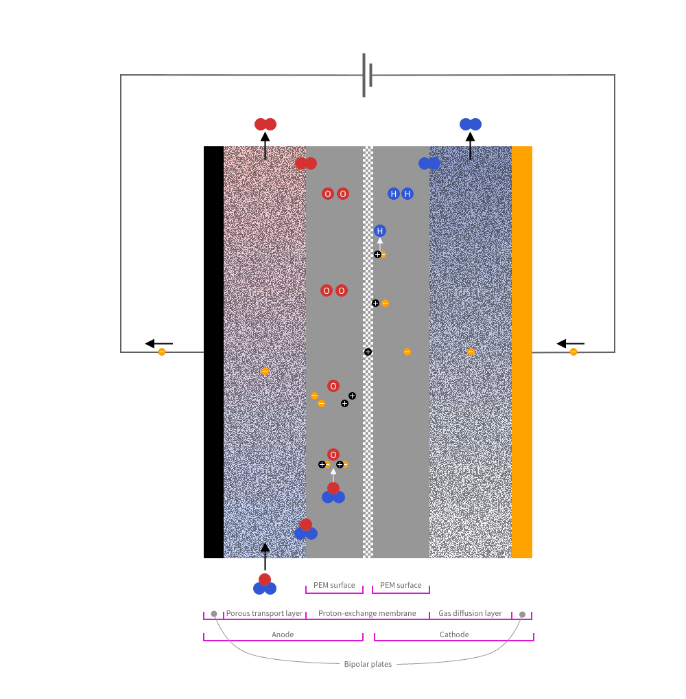
At the anode-side, an oxygen evolution reaction (OER) takes place:
At the cathode-side a hydrogen evolution reaction (HER) takes place:
Each individual reaction occurs within a microscopic region called the triple-phase boundary (TPB). You can think of TPB as a point where the reaction happens because all necessary conditions are met simultaneously. For OER, this means that a water molecule comes into contact with the catalyst and the polymer electrolyte membrane. For HER, it means that a hydrogen ion comes into contact with the catalyst and the polymer electrolyte membrane.
One of the most significant advantages of PEM electrolysis is its high efficiency. Currently, the hydrogen produced has an energy value of up to 80% of the electrical energy supplied. The efficiency is expected to be even higher in the coming years—up to 86% by 2030.
Another advantage to PEM electrolysis is its ability to cope with rapid changes in the current supply, which is a challenge with some renewable energy sources such as solar and wind.
But PEM electrolyzers also have their share of problems.
PEM electrolyzers require platinum and iridium oxide as catalysts. They are scarce and precious metals. For comparison, gold is 40 times more abundant in the Earth’s crust than iridium.
So, to reduce the amount needed, a supporting structure of a cheaper material is coated with a thin layer of metals. Alternatively, particles of the metals are dispersed onto a porous and electrically conducting supporting material.
However, since the total surface area of a catalyst in an industrial application is quite large, the cost of catalysts is still significant. And worse, most of it is never used in the reactions because they are not at the triple-phase boundaries.
So the main challenge of the PEM electrolyzer is to further reduce the use of platinum and iridium oxide in relation to the generated current.
The oxygen evolution reaction and the hydrogen evolution reaction result in gas that needs to be quickly transported away from the catalyst. Otherwise, the gas molecules may block the reactions.
The porous material between the electrodes and the polymer electrolyte membrane dissipates the gases. Yet, on the anode side, problems can arise with oxygen gas not being removed efficiently enough, thus forming gas bubbles in the water, instead.
So another challenge of the PEM electrolyzer is to further improve gas transportation away from the catalytic surfaces.
A carbon nanofiber (CNF) is a carbon-made material so thin that its diameter is measured in nanometres (1 nm = 0.001 µm). Its length is tens of thousands of times longer than its diameter. Typically a CNF has a diameter of 1–100 nm and a length of 1–100 μm.
Smoltek has developed and patented a technology to produce CNFs with extreme precision by chemical vapor deposition (CVD). The technique allows the creation of straight rows and columns of vertical CNFs.
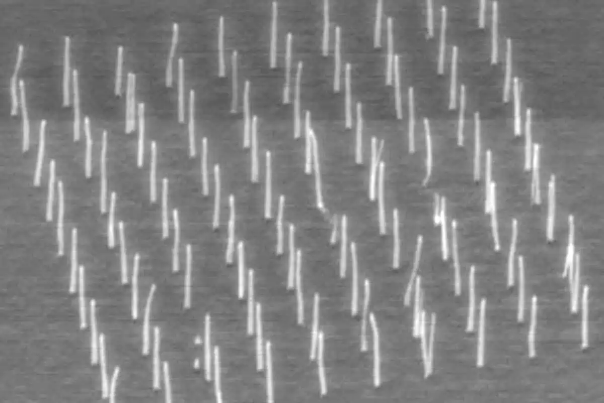
In addition, the technique allows nano-particles, such as a few atoms of platinum or iridium oxide, to be placed on each individual fiber. In conjunction with CNFs electrical conductivity with low resistance, that can be used to solve both issues of the PEM electrolyzer.
The solution is simple. Start from the porous material that will diffuse the gas that will be formed. On its surface towards the membrane, place a large number of CNFs arranged in rows and columns. Attach to each of them nano-particles of the catalytic metal. Embed the prepared CNFs in the polymer electrolyte membrane. Each CNF becomes a “crucible” where the reaction takes place.
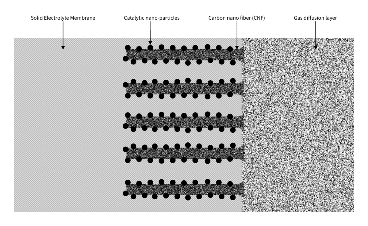
The advantage of this is that the amount of platinum or iridium oxide needed is significantly reduced, as very little of these rare and expensive metals are used and only where they are instrumental.
Moreover, the array of CNFs improves the gas transport, particularly on the anode side where the problem of gas bubbles in water blocking the transport may occur.
This technology produces two to three times more hydrogen compared to existing technology. This is because two to three times more catalyst particles can be in contact with the membrane simultaneously. This, in turn, can lead to savings of up to 30 percent for hydrogen production plants.
It’s not only the PEM electrolyzer that uses an ion exchange membrane (IEM) such as a polymer electrolyte membrane. They are also used in fuel cells. Thus, Smoltek’s CNF solution applies to those as well.
Read more about how carbon nanofibers can improve PEM electrolyzers in our whitepaper Introducing Smoltek Electrolyzer Technology.
Your data will be handled in compliance with our privacy policy.
IR Blog Posts

January 15, 2025
When experts talk about the energy systems of the future, they often come back to one specific number: 0.1 milligrams per square centimeter (0.1 mg/cm²). This seemingly insignificant number could be critical to moving green hydrogen from a promising concept to an economic reality.
IR Blog Posts

January 16, 2025
In the race to make green hydrogen economically viable, researchers worldwide are pursuing the seemingly impossible: reducing iridium use in PEM electrolyzers by 95%. As Smoltek gets closer to this holy grail of 0.1 mg/cm², we examine how other technologies measure up.
IR Blog Posts

April 22, 2025
While traditional development processes often progress at a measured pace, truly disruptive technologies, such as Smoltek’s Porous Transport Electrode (PTE), can dramatically compress timelines. When faced with potentially market-changing innovations, industrial enterprises must choose between maintaining the status quo, slow internal development, or embracing partnership with innovative companies like Smoltek Hydrogen.
IR Blog Posts

September 5, 2024
Smoltek’s focus on qualified research places it firmly in the Explorer quadrant of the R&D Evaluation Matrix, a model for assessing a company’s research and development strategy. Discover why this matters to investors and how Smoltek translates groundbreaking research into valuable business opportunities.
IR Blog Posts

April 14, 2025
Taking a breakthrough technology from the lab bench to the world market often requires collaboration with large industrial enterprises. In this interview, Ellinor Ehrnberg, president of Smoltek Hydrogen, explains how the company aligns its own development with that of potential buyers while navigating the complex journey from initial interest to strategic partnership.
News

September 13, 2024
Smoltek is a Gothenburg-based materials technology company that specializes in research and development of applications based on carbon nanofibers, which can create new products with revolutionary properties.